II.1.4. Arcs
To draw an arc in the Drawing Area, the user must press the Add Arc button from the Drawing Panel or select the Add Arc command from the Modeling menu. Then, the user must click on the start node and then on the end node. The implementation in the PN Toolbox of PN models complies with the basic rule: an arc of a PN can only connect a place to a transition (pre-arc) or a transition to a place (post-arc), but never two nodes of the same kind. The role of splitting arcs in two categories (pre- and post-arcs) will become apparent below, when talking about inhibitor arcs.
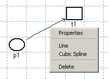
Fig. II.6. The uicontext menu of an arc.
By default, an arc is represented as a straight arrow between the two selected nodes of the net. While in Draw Mode and no button from the Drawing Panel is pressed, a right click on an arc of the net opens a MATLAB uicontext menu (fig. II.6) that allows: (i) modifying the graphical representation in the Drawing Area (Line command for a straight line or Cubic Spline command for a curve), (ii) deleting the arc (Delete command) and (iii) opening the Edit Arc dialogue box (fig. II.7) that lets the user modify the properties of the arc as a MATLAB object (Properties command).
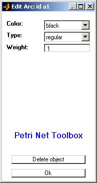
Fig. II.7. The Edit Arc dialogue box for modifying the properties of an arc.
The Edit Arc dialogue box may be also opened by one of the procedures (EA1) or (EA2) described below, followed by a click on the desired arc. (EA1) consists in selecting the Edit Objects command from the Modeling menu; (EA2) consists in pressing the Edit Objects button from the Drawing Panel.
Each arc is uniquely identified with an id that is automatically assigned by the PN Toolbox and cannot be changed by the user. This id appears in the title bar of the Edit Arc dialogue box.
The option Color displays the color used for drawing the arc. By default, this color is black, but the user can select another one from a list of eight predefined colors. Using different colors for the arcs of a net might be helpful for complex topologies (e.g. for highlighting different phases requested by a multi-step design procedure).
The option Type displays the type of an arc. By default, the type of an arc of a PN model is regular, but the user can change it into bidirectional or inhibitor, if necessary. A regular arc represents the standard connection between two nodes of different types. A bidirectional arc is equivalent to a pair of arcs with the same weight, one connecting a place to a transition and the other one connecting the same transition to the same place. The graphical representation of a bidirectional arc is a line with arrows at both ends.
An inhibitor arc can connect only a place to a transition. The transition is enabled only if the number of tokens in the input place is strictly smaller than the weight of the inhibitor arc. The graphic representation of an inhibitor arc is a line between the two nodes ending with a small circle (near the inhibited transition).
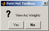
Fig. II.8. The View Arc Weights dialogue box.
The option Weight displays the weight (multiplicity) of the arc. By default, the weight of an arc is equal to 1, but the user can set this field to a positive integer value.
By default, the weights of the arcs in a net are not shown in the Drawing Area. At any stage of PN drawing, the user can visualize the current values of the weights for all the arcs in the net by selecting the Arc Weights command from the View menu. This command opens the dialogue box presented in fig. II.8 and the user must click the Yes button.

