II.1.1. Overview
The PN Toolbox provides a set of commands for building a PN model, which are accessible from the Modeling menu or from the corresponding buttons in the Drawing Panel. The model may be easily drawn, in a natural fashion, in the Drawing Area. The user can also have a read/write access to the properties of the net nodes and arcs by opening the dialog box associated with the object selected in the Drawing Area. In addition, the PN Toolbox allows the assignment of priorities and/or probabilities to conflicting transitions.
The Drawing Area displays a grid with dotted gray lines. The user may hide or show these lines by using the command View/Show Grid or by pressing the corresponding button from the Quick Access Toolbar. The nodes of the PN may be placed only in the grid cells; each cell can contain a single net node. This way, each node is uniquely characterized by its coordinates in the Drawing Area.
A PN model created in the PN Toolbox is saved as an XML file. Besides the automatic generation of the XML file of a model, any text editor can be used to produce such a file if the user complies with the syntax given in Appendix A.
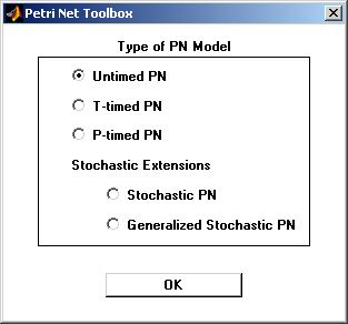
The first step in the creation of a new model is to define its type. By selecting the type of the PN, some of the work variables are automatically changed. This is because the simulation and analysis procedures differ from one type to another. The drawing board of a new model may be opened in the Drawing Area by selecting the File/New Model command or by pressing the New button from Quick Access Toolbar. This command opens a dialog box (fig. II.1) which permits the selection of the type of model to be built. The default type is Untimed PN.
A previously created model may be loaded from the disk by means of the command Open available under the File menu or by pressing the Open button from the Quick Access Toolbar. Changes in an existing model can be done directly in the GUI while in Draw Mode, or by editing the corresponding XML file.
If a model is already loaded in the window, the Drawing Area is cleared by selecting the command File/Close Model.
Fig. II.1. The dialogue box for selecting the type of a PN model.

